

Technical Information & Specifications
ShockWatch Product Specifications
Technical Information for ShockWatch Labels
Frequency vs. Duration
The amount of time required for an impact to happen is described in two ways; frequency and duration. Frequency describes the time as compared to cycles per second and the unit of measure is called Hertz (Hz). Duration describes the time as compared to seconds and the usual unit of measure is milliseconds (ms).
The mathematical expressions related to these two terms are:
1ms = .001 seconds
1Hz = one cycle per second
Duration = (1 / Frequency) / 2
Frequency = (1 / Duration) / 2
| To convert Duration to Frequency, the calculation is as follows: Duration = (1 / Frequency) / 2 Example: Convert 500Hz to Duration |
To convert Frequency to Duration, the calculation is as follows: Frequency = (1 / Duration) / 2 Example: Convert 10ms to Frequency |
ShockWatch Activation Curves
The left side of the Frequency vs. Duration curve shows a linear scale and is titled “G” or “G-level.” This is the acceleration scale. A “G” is a multiple of the acceleration due to gravity (32.2ft/s2, or 9.8m/s2). Five (5) G’s equals five (5) times the acceleration due to gravity.
The bottom side of the page shows a linear scale that is titled “t.” This is the duration scale and its unit is milliseconds. One millisecond is 1/1000 of a second. The most critical thing to observe from the curves is that as duration decreases, activation acceleration increases.
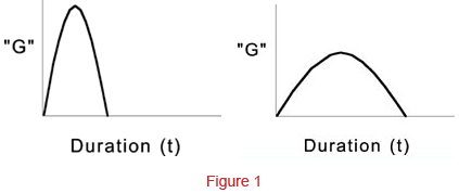
The reason behind this is that our shock curves are based on a half-sine shock pulse. The area under the shock pulse is known as v, or rather, the change in velocity. The “Δ“ v is actually the phenomenon that activates a ShockWatch device or causes damage to a product. If you shorten the duration (make the shock pulse thinner) you must make it taller (higher G) to keep approximately the same area under the curve (Δ v). Figure 4 features two shock pulses; the first one is wide and short and the second one is tall and skinny. But they both could be used to describe the same ShockWatch device because they have approximately the same area under the curve (Δ v). The second shock pulse makes up for its shorter duration with a high “G.”
There is also one other parameter to be aware of. Each ShockWatch has a “minimum G” threshold that must be exceeded before it will activate. You can determine this “minimum” G for each ShockWatch device by looking at the shock curves. It is the left most “G-level” value on the curve. It is the “G-value” where the shock curve intercepts, or runs into, the left acceleration scale. If this “minimum G” is not exceeded, regardless of the duration or the Δ v, the ShockWatch will not activate.
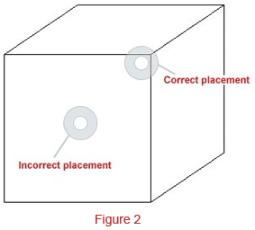
ShockWatch Label Placement
The correct placement of a ShockWatch label is paramount to achieve proper device operation. A ShockWatch label placed in the wrong position on a package can alter that device’s response characteristics and cause erratic results.
Whenever possible, the ShockWatch label should be placed on as rigid an area as possible. The reason for this is that if the surface to which the label is affixed is flexible, or can flex, it will dissipate an indeterminate amount of shock. The selection guide for ShockWatch devices is based on the assumption that the label is placed on a package at a position that has minimal flex. If a ShockWatch label is placed in a non-rigid position, its activation response will not correlate with the selection guide.
Typically, the most rigid area of a container (box) is at or near a corner. The most flexible area of a container is the center of a side. To prove this to yourself, press against the center of one side of a corrugated container. You will see that it easily gives way and flexes. Now, press against that same side but at a point near the junction of that side with one of the other sides (corner). You will see that there is considerably less flex.
In conclusion, if a ShockWatch customer reports erratic results in using the ShockWatch labels, the first item to check is the placement of the label.
Packaging
As you well know, the packaging of an item plays a very important role in ensuring that the product will reach its destination without damage. But do you know specifically how packaging protects the contents? The assumption is that packaging simply absorbs or dissipates shock. Actually, packaging uses physics to alter shock or impact so that it doesn’t render damage to the contents. Here is how.
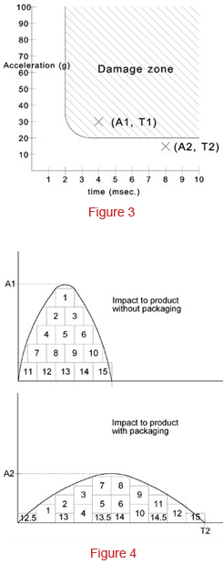
Figure 3 shows a damage boundary curve (DBC). A DBC can be developed for every product made. A DBC shows what shock is required to damage a product. Any impact whose characteristics fall within the damage area of the DBC will damage that product. For instance, on the DBC shown, an impact of 50G @ 5 ms would damage the product because that impact is within the damage area. For the same DBC, an impact of 10G @ 5 ms would not damage the product because it is outside the damage area. Two interesting characteristics of a DBC are 1) it clearly shows that for all products, there is a minimum acceleration, and 2) a minimum time duration that must be exceeded in order to render damage to a product.
Figure 4 shows two shock pulses. The top pulse represents what a product is exposed to when it is dropped a specific height with no packaging. The bottom pulse represents what a product is exposed to when it is dropped from the same height but is protected by packaging. Each pulse occupies approximately the same area, as represented by the numbered squares. This area is called delta V, or rather, the change in velocity experienced by the product when it was dropped. v is purely a function of the drop height and since drops from the same height generated these shock pulses, they have the same v.
So how can two shock pulses have the same v, but be shaped so differently? When the product was dropped with packaging, the first thing to hit the ground was the box. When the box touched the ground, it came to a stop very quickly. The amount of time required for an object (box) to stop once it has impacted another object (ground) is what we call the time duration of an impact. Although the box had stopped, the contents continued to move by compressing the packaging foam. Thus the contents had a longer time duration. So if the box and contents were experiencing the same v, but the contents experience a longer time duration, the peak acceleration seen by the contents had to be lower.
Refer to the DBC on figure 3. You will see two points. One is marked “A1, T1″and the other is marked “A2, T2.” “A1, T1” represents the shock pulse without packaging shown on figure A. As you can see “A1, T1” is within the damage area of the DBC and thus would damage the product. “A2, T2” represents the shock pulse with packaging shown on figure 4. “A2, T2” is outside of the damage area and thus would not damage the product. So in effect, what the packaging did was to increase the time duration, lower the peak acceleration, and get the impact out of the damage area of the DBC.
So packaging really just changes the characteristics of shock to not damage the contents.
ShockWatch Activation Angles
All of the ShockWatch activation curves we publish are based on the ShockWatch receiving an impact at a 45° angle. ShockWatch monitors are most sensitive to impacts at this angle. There does exist, however, a slight deviation in the response of a ShockWatch monitor to an impact at an angle of 90°. In most applications, this deviation is not relevant. However, there are some applications where precise impact values at specific angles are required.
The deviation in a ShockWatch monitor’s response due to the change in angle generally follows this equation:
90° acceleration (G) value = 45 degree acceleration (G) value / .7071
Example: 45° acceleration value for a L-65 at 10ms = 46G
90° acceleration value = 46G / .7071
90° acceleration value = 65G
Knowing this characteristic of ShockWatch monitors can be a benefit. For instance, you may have a customer who has a specific engineering application where he wants an indicator that will react at a value that does not coincide specifically with one of our standard ShockWatch monitors. It is sometimes possible to simply change the orientation of the monitor so as to achieve the sensitivity required at a specific angle.
ShockWatch Activation Equations at 45° Acceleration
| Product | Angle | Equation |
| L-30 | 45° | G+367.2 / t + 102.5 |
| L-35 | 45° | G = 299.8 / t + 81.5 |
| L-47 | 45° | G = 233.1 / t +52.7 |
| L-55 | 45° | G = 215.0 / t + 40 |
| L-65 | 45° | G = 201.1 / t +25.1 |
To calculate the 90° value, use the following equation:
90° acceleration (G) value = 45 degree acceleration (G) value / .7071
Manufacturing Quality Specification
The quality specification used in the manufacturing process of the ShockWatch tube is as follows:
- U.S. Military Specification (Mil Spec)
- Mil Spec 105D
- 2.5% Cumulative AQL
This specification is a recognized means of statistically sampling manufactured goods and is acceptable to ISO 9001 concerned.
ShockWatch Labels, Clips and Tubes
| Operating Temperature | -13°F / -25°C to 176°F / 80°C |
| Size | Label 3.8″/96.52mm x 3.8″/96.52mm Double Clip 1.9″/49.52mm x 1.1″/28mm x 0.2″/4.31mm (25–37.5G) 1.6″/42.69mm x 1.1″/27.95mm x 0.1″/3.31mm (50–100G) Mini Clip Double 1.4″/35.72mm x 0.5″/12.85mm x 0.2″/4.19mm (25–37.5G) 1.4″/35.72mm x 0.5″/12.85mm x 0.1″/2.97mm (50–100G) |
| Sensitivity | Available from 10 to 100G and sensitive to impacts on 360° axis |
| Responsiveness | Responds to single impact, omni-directional |
| Duration | Ranges 1 to 50ms |
| Adhesive | Acrylic |
| Shelf Life | Scotch 468 Adhesive – 2 years from date of sale, when stored at standard temperature and pressure (20°, 1 ATM) |
DropSpot
| Operating Temperature | -13°F / -25°C to 176°F / 80°C |
| Size | 3.5″ / 88.9mm x 3.5″ / 88.9mm x 0.2″ / 5.1mm |
| Sensitivity | 10G, 15G, 25G |
| Responsiveness | Bidirectional only |
| Duration | Ranges 1 to 50ms |
| Adhesive | 5 mil high tack acrylic |
| Shelf Life | Scotch 468 Adhesive – 2 years from date of sale when stored at standard temperature and pressure (20°C, 1atm) |
TiltWatch
| Operating Temperature | – 40°F/- 40°C to +140°F/+60°C |
| Humidity Tolerance | 5% to 99% non-condensing |
| Size | 2.9″ x 2.7″ x 0.2″ |
| Activation Angle | 80°+/-5% from vertical |
| Monitoring Range | Single plane |
| Composition | Rigid polystyrene housing with stainless steel indicator |
| Installation | Pressure sensitive adhesive or holes to accommodate screws, nails, and staples |
| Adhesive | 5 mil high tack acrylic |
| Shelf Life | 2 years from date of sale |
TiltWatch Plus
| Operating Temperature | – 40°F/- 40°C to +140°F/+60°C |
| Humidity Tolerance | 5% to 99% non-condensing |
| Size | 4.6″ x 4.6″ x 0.3″ |
| Activation Angle | 10° increments from 30° axis (+/-5%) |
| Monitoring Range | 360° monitoring within a single plane |
| Composition | Clear PTE housing and brass, non-magnetic indicator |
| Installation | Pressure-sensitive adhesive exposed when liner and arming pin are peeled away |
| Adhesive | 1 mil high tack acrylic |
| Shelf Life | 2 years from date of sale |
Impact and Environmental Recorder Specifications
ShockLog 298
Product Specification
| Operating Temperature Range | -40°F / -40°C to 185°F / 85°C |
| Size | 4.8″ / 123mm x 3.1″ / 78mm x 2.2″ / 55mm |
| Weight | 1.1lbs / 515g (without battery) |
| Battery | 2 x 3.6V Lithium Thionyl Chloride 2 x 1.5V Alkaline Size AA |
| Scale Factor Accuracy at 5G | +/- 2% |
| Additional Error Other Ranges | +/- 2% |
| Acceleration Range | +/- 1 to +/- 200G |
| Cut-off Frequency Options (Programmable) | 10Hz, 40Hz, 50Hz, 90Hz, 120Hz, and 250Hz |
| Wake-up, Warning and Alarm Threshold (% of Range) |
5–95% |
| Wake-Up Time | 0.25mS |
| External Power Source Option | 4.5V min / 30V max |
Humidity / Temperature Specification
| Temperature Measuring Range | -40°F / -40°C to 185°F / 85°C |
| Temperature Accuracy | -2 / 2°C |
| Humidity Measuring Range | 0 – 100% RH |
| Humidity Accuracy | -3 / 3% RH |
| Dew Point Measuring Range | -40°F / -40°C to 185°F / 85°C 0-100% RH |
| Dew Point Accuracy | -2 / 2°C |
GPS Specification
| Sensitivity | 157dBm re-acquisition 148dBm cold starting |
| Fast TTFF | 1s / 29s (Hot/Cold start) |
| Channels | 65 |
| Hypothesis testing per second | 8,000,000 time-frequency |
| High Accuracy Position | 2.5m CEP Velocity 0.1m / sec |
RF Specification
| Operating Frequency | 2.4GHz |
| Max Output Power | Up to +10dBm |
| Receiver Sensitivity (PER 1%) | Up to -100dBm |
| RF Data Rate | 250,000bps |
| Pocket Data Rate | Up to 125kbaud |
RF Base Specification
| Radio | ZigBee Module |
| Transmission Frequency | 2.4GHz |
| Transmission Distance | Up to one mile |
| Power Levels | 10mW (10dB) |
| Data Transmission Rates | 115,200 baud |
Tilt & Roll (Internal) Specification
| Tilt Range Monitored | + / – 180° |
| Resolution | 0.1° |
| Transverse Sensitivity | 5% |
ShockLog 298 Accessories
HPT Environmental Sensor Specification
| Temperature Measuring Range | -40°F / -40°C to 185°F / 85°C |
| Temperature Accuracy | -2 / 2°C (1 bar unit) -4 / 4°C (2 bar unit) |
| Humidity Measuring Range | 0 – 100% RH |
| Humidity Accuracy | -3 / 3% RH (1 bar unit) -6 / 6% RH (2 bar unit) |
| Pressure Measuring Range | 0 – 1.1 bar (standard) 0 – 2.1 bar (optional) |
| Pressure Accuracy | -10 / 10 Mbar (1 bar unit) -60 / 60 Mbar (2 bar unit) |
eTrak Specifications
| Operating Temperature Range | -40°F / -40°C to 185°F / 85°C |
| Size | 6.3″ / 160mm x 9.8″ / 250mm x 1.6″ / 40mm |
| Weight | 1.53 lbs / 696g |
| Regions | Global provided GSM network coverage available |
ShockLog 248
Product Specifications
| Operating Temperature Range | -40°F / -40°C to 185°F / 85°C |
| Size | 3.3″ / 84mm x 3.3″ / 84mm x 2.2″ / 55mm |
| Weight | 1.1lbs / 445g (without battery) |
| Battery | 1 x 3.6V Lithium Thionyl Chloride 1 x 1.5V Alkaline Size AA |
| Battery Life | 12 months |
| Scale Factor Accuracy at 5G | +/- 2% |
| Acceleration Range | +/- 10G, +/- 30G, +/- 100G |
| Cut-off Frequency Options (Factory Set) | 40Hz, 90Hz, and 250Hz |
| Wake-up, Warning and Alarm Threshold (% of Range) | 5–95% |
| Wake-Up Time | 0.25mS |
Factory Fit Specifications – Humitidy/Temperature
| Humidity | 0-100% RH |
| Temperature | -40°F / -40°C to 185°F / 85°C |
| Dew Point | -40°F / -40°C to 185°F / 85°C 0-100% RH |
ShockLog 208
Product Specifications
| Operating Temperature Range | -40°F / -40°C to 185°F / 85°C |
| Size | 3.3″ / 84mm x 3.3″ / 84mm x 2.2″ / 55mm |
| Weight | 1.1lbs / 445g (without battery) |
| Battery | 1 x 3.6V Lithium Thionyl Chloride 1 x 1.5V Alkaline Size AA |
| Case Material | Aluminum |
| Acceleration Range | +/- 10G, +/- 30G, +/- 100G |
| Cut-off Frequency Options (Factory Set) | 40Hz, 90Hz, and 250Hz |
| Time Slot Length | 10 seconds to 1 hour |
Factory Fit Specifications – Humitidy/Temperature
| Humidity | 0-100% RH |
| Temperature | -40°F / -40°C to 185°F / 85°C |
| Dew Point | -40°F / -40°C to 185°F / 85°C 0-100% RH |
Lets Talk!
We are always happy to hear from you regarding questions and/or technical help. Just give us a call on 0207 739 3344 or fill out our form below.